


Our Cleanroom Manufacturing Facilities
Clean Room, Clean Manufacturing.


We combine 700 years collective knowledge & experience bring tangible savings to your new projects & help refine and develop existing products.
Learn More »

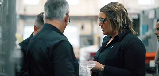
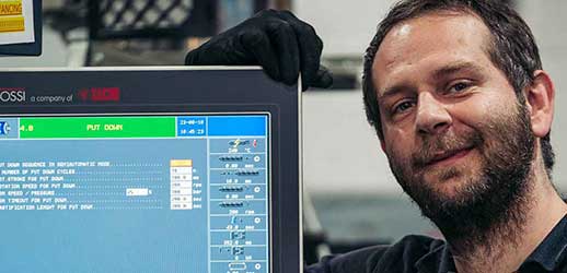
Building a great business with great knowledge, people and passion.
Learn More »
We really care about the service we offer our customers. We will be a dependable partner in achieving a competitive advantage in today’s market.
Learn More »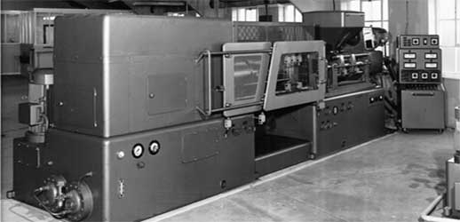
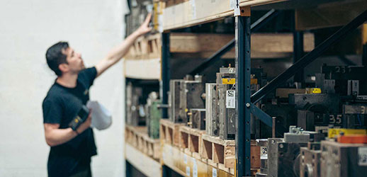
Nordell is one of the UK’s leading independent Plastics Manufacturing and Design refinement companies. It’s over 50 years since its first company registration in 1968 as Component Moulders at King Edward Close Worthing.
Learn More »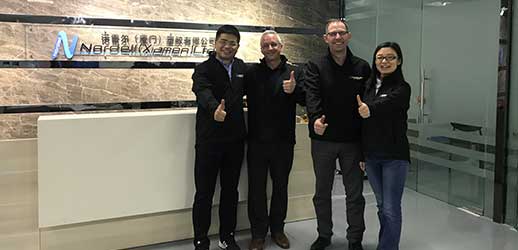
Nordell (Xiamen) was formally registered in 2018 as a working partnership between Sunled China and Nordell UK. We drive innovation by combining years of manufacturing and engineering knowledge.
Learn More »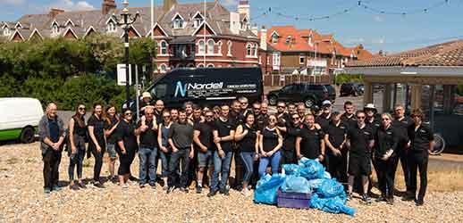
We employ over 80 people from the local community and are active members of the local Sussex Chamber. We believe in supporting our local community and are pleased to support a number of community initiatives.
Learn More »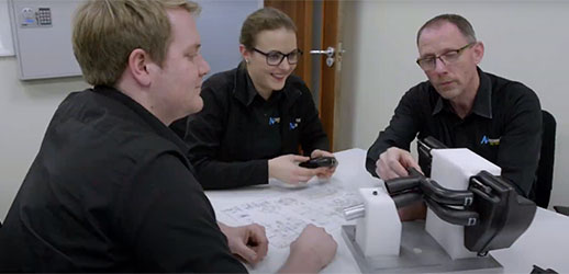
We have a range of Videos available to succinctly explain some of our key services.
Learn More »
Whether it is our people, our facility and machinery, the products or the industries we manufacture for you will find a collection of exciting and interesting news stories and articles below.
Learn More »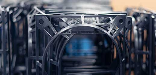
At Nordell our Company Mission statement and Core values define the way we work
Learn More »
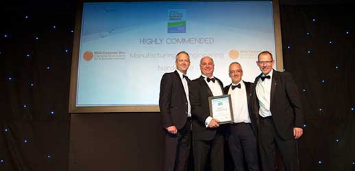
We are an award winning company - and do our bit to sponsor and promote others.
Learn More »


The Nordell Customer Charter is a promise to our customers, setting the expectations of how we will do business
Learn More »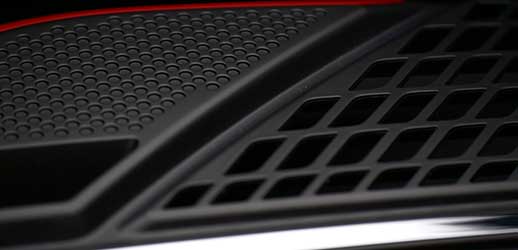
We really care about the service we offer our customers. “We do what we say, and we do it well”.
Learn More »
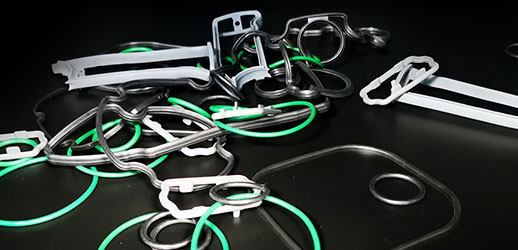
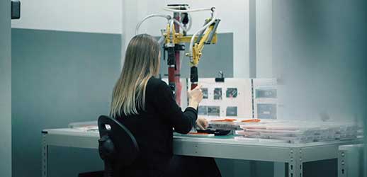
We offer a full range of complimentary manufacturing services in addition to our principal lastic injection moulding business.
Learn More »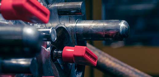
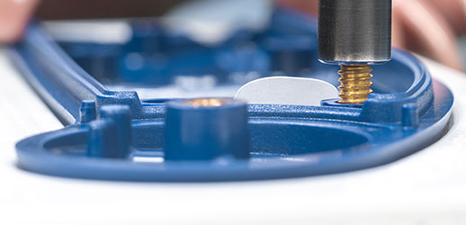
Value added services for complete or part-assembled products
Learn More »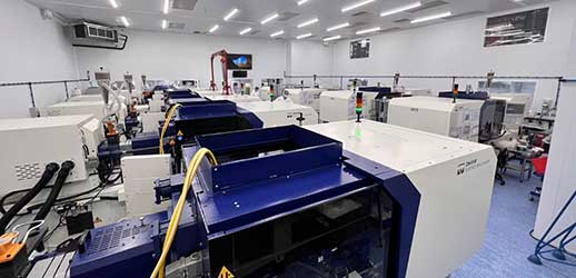

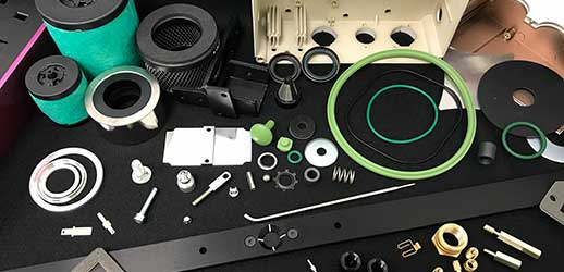
Helping you to reduce supply chain complexity and risk.
Learn More »
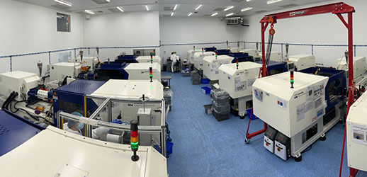
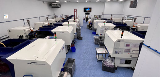
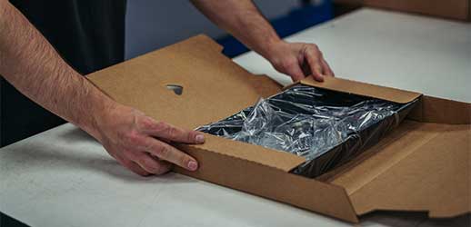
Offering a complete Cleanroom solution from Injection moulding through to assembly & final packing.
Learn More »
Helping you to reduce supply chain complexity and risk.
Learn More »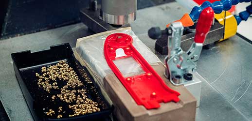
Our clients, customers and partners operate across a wide variety of sectors and global markets. We have a growing reputation for being able to apply our skills and knowledge across sectors and industry types and love the challenges this diversity brings.
Learn More »


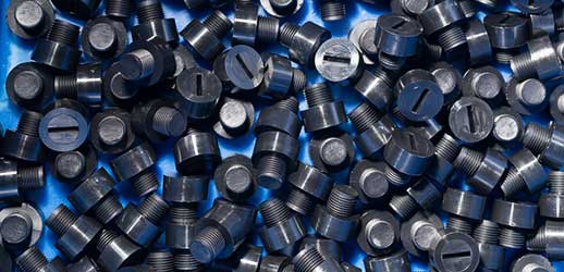
The electronics sector demands specialist plastics critical for high or low conductivity. Nordell is able to help you select the right product for your requirements.
Learn More »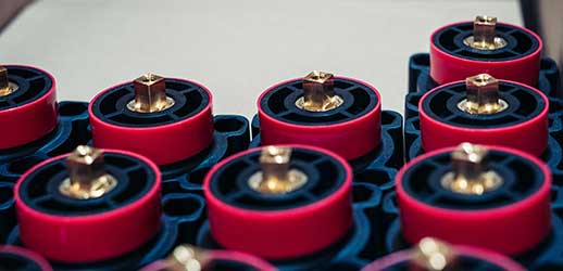


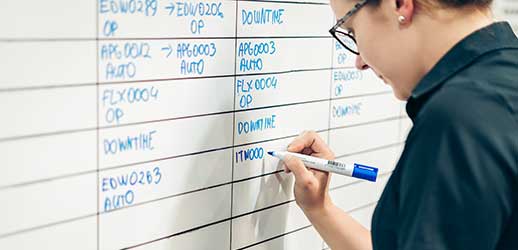
Keeping waste to a minimum with tight process management and training.
Learn More »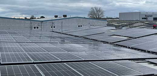
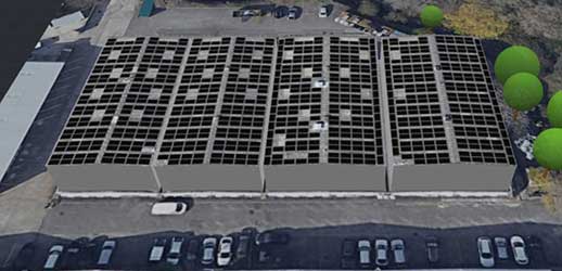
Partnering with leading companies in the Environmental sector.
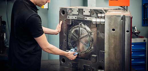
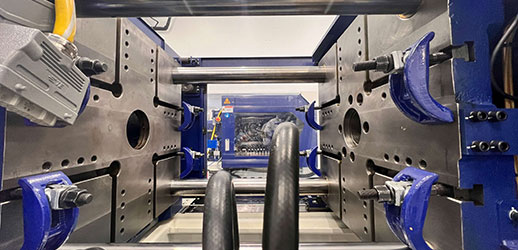
Learn More »The process of plastic injection moulding takes place in an injection moulding machine which in the main consists of the clamping unit, injection unit, and the mould tool.
At the clamping stage, the two halves of the mould are closed before injecting the molten plastic. The tool is clamped together after the molten material has dwelled in the tool cavity cavities. The clamping unit is responsible for:
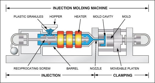
The clamping unit consists of:
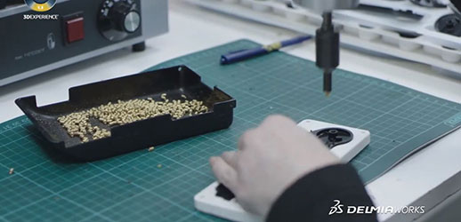
At the injection stage, the plastic granules are heated and melted then delivered to the mould via the injection unit. The injection unit is responsible for:
The injection mould machine has various parts:
Once the molten plastic is in the mould, it is allowed to dwell inside the cavities. The injection pressure is replaced by the holding pressure where the molten plastic solidifies.
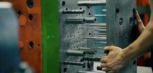
Cooling starts once the molten plastic comes in contact with the surface of the cavities. Cooling is facilitated by the cooling system inside the mould which removes the heat. After cooling the part for sufficient time, the two halves of the mould are separated, and the part is ejected.
At the ejection stage, the cooled part is separated from the mould. The ejection system, which is in the clamping unit, enables the removal of the moulded part from the cavities.
The last step in the production of moulded parts is trimming, where any excess plastic is removed.
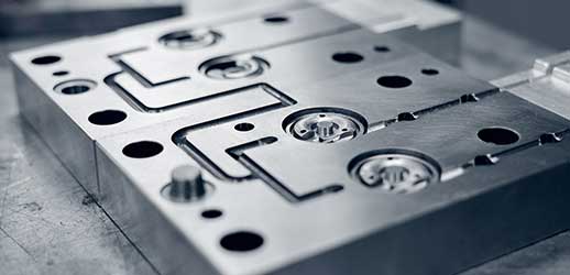
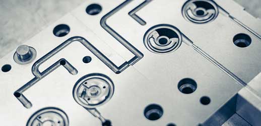
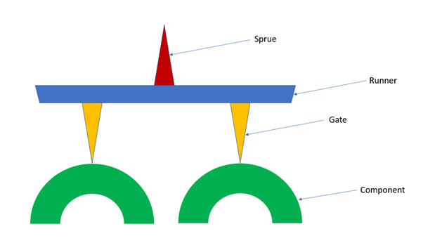
During injection of the molten plastic, the mould channels (sprue, runners, and gates) are filled. After cooling, the excess plastic materials adhere to the part which needs to be removed.
Phone: +44 1903 235 765
Monday - Thursday: 08:00 - 17:30 & Friday 8.00 - 12.00
Monday - Thursday: 08:00 - 17:30 & Friday 8.00 - 12.00
Email: enquiries@nordell.co.uk
Monday - Thursday: 08:00 - 17:30 & Friday 8.00 - 12.00
